CAN FD-Revolutionizing the Way Modern Vehicles “Talk”
When Bosch officially released the CAN bus protocol in 1986, it started a revolution that unlocked numerous possibilities for innovation in the automotive ecosystem. Today, the protocol has evolved well beyond its inception to becoming an integral bus standard that shapes the future of all modern vehicles.
The CAN protocol enhances the data transmission pattern in vehicles by providing a no -latency, collision-free bus, optimized for real-time data transfer. Today, any machine that moves utilizes CAN – whether it’s cars, trucks, boats, aircraft, or robots and is increasingly dominating other industries as well.
CAN FD is a newer extension to the CAN protocol that allows the system to handle more data at a faster rate.
Why CAN FD?
The rise of technology and integration of sophisticated electronics has led to an increase in the vehicle functionality. The need came for improving the bandwidth requirements for transmitting larger payload at a faster bit rate. As a result, the CAN FD protocol was developed by Bosch (with industry experts) and was released in 2012. It was significantly improved during the standardization process; both Classical CAN and CAN FD are internationally standardized in ISO 11898-1:2015.
CAN FD offers the following benefits over Classical CAN:
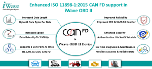
- Increased Data Length: CAN FD supports up to 64 data bytes per data. This reduces the protocol overhead and leads to an improved protocol efficiency.
- Increased Speed: CAN FD supports dual bit rates: The arbitration bit-rate limited to 1 Mbit/s and the data bit-rate, up to 5 Mbit/s are achievable.
- Improved Reliability: CAN FD uses an improved cyclic redundancy check (CRC) and the “protected stuff-bit counter.” This guarantees that all single failures are detected under all conditions, vital in safety-critical applications like vehicles and industrial automation.
- Enhanced Security: With higher bandwidth, CAN FD enables authentication via the Secure Onboard Communication (SecOC) module, which makes CAN FD highly reliable for real-time data.
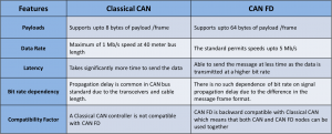
Here is an illustration stating the key differences between Classical CAN and CAN FD:
How CAN FD works?
The CAN FD protocol introduces an adjusted CAN data frame to enable the extra data bytes and flexible bit-rates.
Structure of CAN FD data frames
The messages begin with a start bit and then proceed into the arbitration phase with the control field. When the arbitration is established, the data packet is added. It is finished with CRC, ACK, end of the frame, and IMF sequence. Using a ratio of 1:5 for the bit-rates in the arbitration and data phase and larger payload (64 bytes/frame) improves the protocol efficiency and results in higher throughput.
Classical CAN Frame
CAN FD Frame
Although both Classical CAN and CAN FD frames appear similar at first glance, there is a significant difference that comes with the addition of extra fields and bits to guarantee maximum robustness and reliability of CAN FD.
CAN FD in iWave OBD II Secured Edge Analytics
CAN bus is one of the many protocols used in the OBD II on-board diagnostics standard. The OBD II module reads the CAN bus data and enables real-time analysis of vehicle parameters such as engine performance, fuel efficiency, emission levels, etc. CAN FD is essential and plays a vital role in obtaining high-speed data from the network sensors and ECUs.It provides accurate and reliable data enabling on-time diagnosis and maintenance.
iWave’s OBD II module is powered by the i.MX6ULL Cortex A7 CPU and supports the following CAN interfaces: LS CAN, HS CAN, SW CAN ,RAW CAN & CAN FD. Capability to support 3 CAN ports simultaneously, i.e., CAN FD, LS CAN, HS CAN, and compatibility with all OBD II protocols ensures accurate and reliable diagnostics. The module also supports the SAE J1939 protocol that enables convenient management of heavy-duty vehicles by providing access to the vehicle ECUs to retrieve real-time diagnostics data.
iWave Expertise:
- iWave has integrated CAN-FD with the processor that does not support CAN-FD directly. This gives the flexibility to use the various combinations of the CAN interfaces that is available in the automotive industry.
- The OBD II device supports multiple CAN interfaces and based on the requirements any/combination of the CAN could be enabled.
- iWave application API’s handles the data framing (HS-CAN, LS-CAN, CANFD) to send/receive the data to the vehicle.
iWave OBD II device is now enhanced with CE/FCC, E-Mark, KOMINFO, and GCF certifications. For more details about iWave OBD II product solution
To know more, write to us at mktg@iwavesystems.com or contact our regional partners.


