
Get started with Agilex 7 SoC FPGA (R24C) SOM Development Platform
Unpacking
Remove the Development Platform from box and place above the ESD free area. Use anti-static pad/mat with proper grounding to place the Development Platform. Also make sure that, below deliverables are received without any physical damage.
Development kit contains:
- Agilex 7 SoC FPGA (R24C) SOM Development Platform
- 12V, 14A Power Supply
- Safety guidelines
- USB Debug cable
- Heatsink + FAN
- JTAG cable


SAFETY GUIDELINES
Agilex 7 SoC FPGA SOM
Development Platform
Heatsink+FAN


12V, 14A Power Supply
USB Debug Cable
JTAG cable
Get to know

Agilex 7 SoC FPGA (R24C) SOM – Top view
1. Fan Header
2. Agilex 7 SoC FPGA
3. Configuration selection switch

Agilex 7 SoC FPGA (R24C) SOM – Bottom view
4. Board to Board connector 2
5. Board to Board connector 3
6. Board to Board connector 1

Agilex 7 SoC FPGA (R24C) Development Platform – Top view
01. Firefly Connector**
02. Firefly Power Connector**
03. Board to Board Conn 4**
04. Board to Board Conn 2
05. PMOD Connector 2**
06. JTAG Header
07. RESET Switch
08. PMOD Connector 1**
09. QSFP+ Connector
10. Power ON/OFF Switch
11. Power IN Connector
Note:
*Optional
**Not Supported
12. Debug Port
13. 20 Pin GPIO Header
14. USB OTG Connector
15. Ethernet MAGJACK 1
16. Ethernet MAGJACK 2
17. Display Port**
18. XCVR Config Switch
19. SFP+ Connector*
20. PCIe x 1 Connector**
21. SDI IN HD BNC Jack
22. SDI OUT HD BNC Jack
23. HDMI OUT Connector**
24. CAN Header**
25. HDMI IN Connector**
26. USB Type C Connector*
27. FMC Connector
28. Board to Board Conn 1
29. FMC+ Connector
30. Board to Board Conn 3
31. 12V FAN Header

Agilex 7 SoC FPGA (R24C) Development Platform – Bottom view
32. RTC Battery Holder*
33. Standard SD Connector*
Note:
*Optional
**Not Supported
34. M.2 SATA Connector**
35. SMA Connector 2
36. SMA Connector 1
Heat Sink Integration
iW-RainboW-G51D Agilex 7 SoC FPGA (R24C) SOM Development platform comes with Heatsink+Fan attached to it. Make sure to power up the platform only with Heatsink+Fan attached. Below is the Heatsink+Fan integration procedure for reference.


Heatsink + Fan
Peel off Thermal pad sticker

Boot Switch Setting
Make sure On-Board Switch (SW1) is set properly as shown below image


Debug Port Setting
Connect Type-A end of USB cable to PC and Micro-B end of USB cable to Development platform’s debug Micro USB connector (J13) as shown below.

Powering ON
Connect the Power supply plug to the Power connector (J10) of the Development platform as shown below and switch ON the power supply. Once power is applied to the Development platform, the power LED in the Development platform will glow as shown in the below image.

Warning:
- Do not try to connect any other Power Supply other than supplied along with Agilex 7 SoC FPGA (R24C) SOM Development Platform.
- Do not plug or remove Agilex 7 SoC FPGA (R24C) SOM from carrier board with live power.
- Contact iWave, if power LEDs are not glowing.
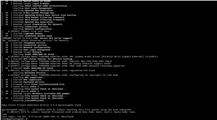
Command Prompt
JTAG Connection
iW-RainboW-G51D Agilex 7 SoC FPGA (R24C) SOM Development platform support JTAG
interface for FPGA Programming and debugging. Use the USB Blaster to connect Carrier Board.
Example USB Blaster which is tested with this Platform is mentioned below.
USB Blaster-2
Part Number : PL-USB2-BLASTER from INTEL
