Get started with i.MX 8 QM/QP Qseven DevKit SOM Development Platform
Unpacking
Remove the Development Platform from box and place above the ESD free area. Use anti-static pad/mat with proper grounding to place the Development Platform. Also make sure that, below deliverables are received without any physical damage.
Development kit contains:
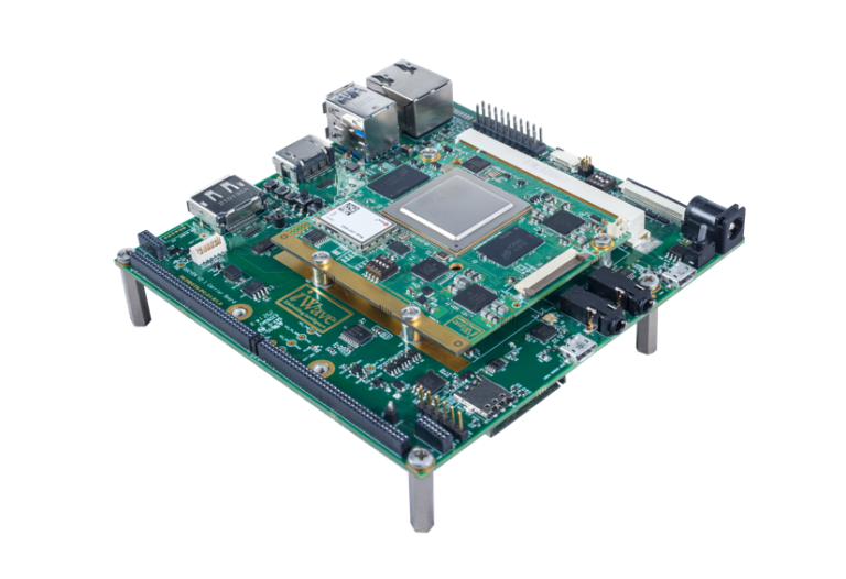
- i.MX 8 QM/QP Qseven DevKit
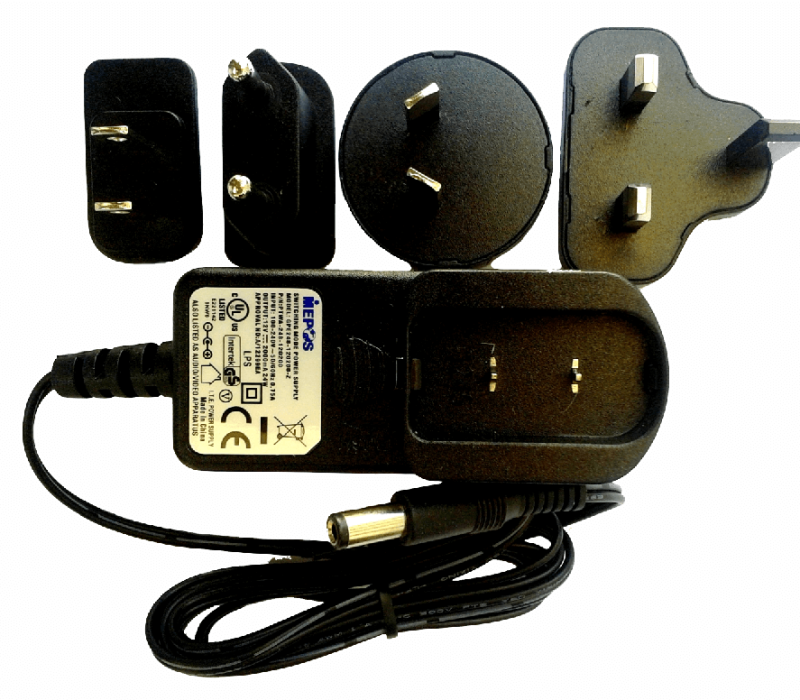
- 12V,2A Power Supply
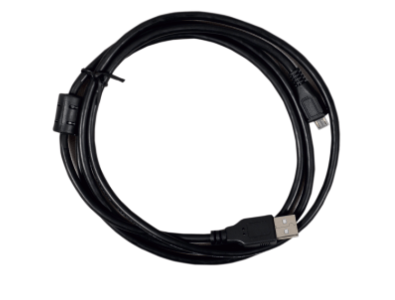
- USB cable (micro-B to standard-A)
- Wi-Fi & BT Antenna
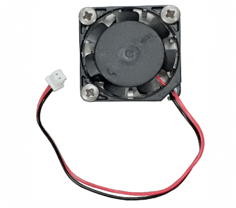
- Fan
- Safety guidelines
SAFETY GUIDELINES
i.MX 8 QM/QP Qseven DevKit
12V, Power Supply
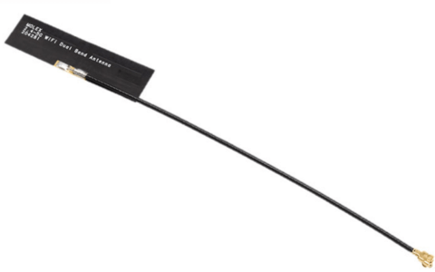
Wi-Fi BT Antenna
Fan
USB OTG cable*
Get to know
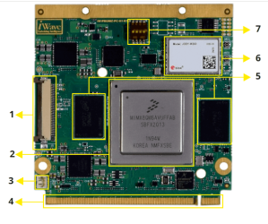
i.MX 8 QM/QP Qseven Som Top view
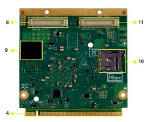
i.MX 8 QM/QP Qseven Som Bottom view
1. MIPI CSI-2 Camera Conn.
2. i.MX 8 QM SoC
3. FAN Conn.
4. Qseven Edge
5. LPDDR4
6.Wi-Fi & BT Module
7.Boot media Switch
8.Expansion Conn.2
9. eMMC
10.Micro SD Conn.(Optional)
11.Expansion Conn.1
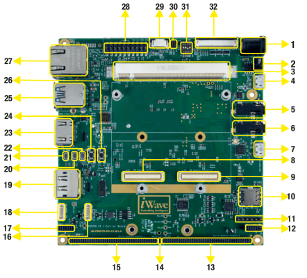
i.MX 8 QM/QP Qseven Devkit– Top view
1. Power IN Jack
2. Power switch
3. Q7 MXM Connector
4. USB OTG Connector
5. Audio OUT Jack
6. Audio IN Jack
7. Debug UART Connector
8. SOM Expansion Connector 1
9. SOM Expansion Connector 2
10. Nano Sim Connector
11 .Data UART Header
12. Power I&O Connector2
13. Carrier Exp. Connector-2
14. Power Header*
15. Carrier Exp. Connector-1
16. CAN Header
17. Power I&O Connector-1
18. FAN Header
19. Display Port Connector*
20. THERM SW
21. SLP SW
22. WAKE SW
23. HDMI Connector
24. RESET SW
25. USB 3.0 Connector Stack
26. ON/OFF SW
27. Ethernet Jack
28. JTAG Header
29. CAP Touch Connector
30. Config Connecter*
31. Board Config. SW
32. 7″ RGB Display Connector
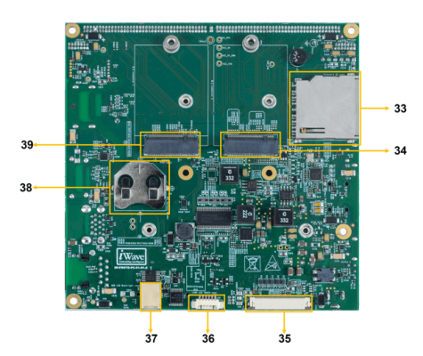
STM32MP13x OSM-based SBC – Bottom view
33. SD/MMC Connector
34. M.2 PCIe Connector
35. LVDS LCD Connector
36. RES Touch Connector
*Not Supported
37. CAP LCD BL Connector
38. RTC Battery Connecter
39. M.2 SATA Connector
Boot Switch Setting
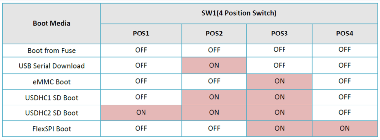
Make sure On-Board Switch (SW1) is set properly as shown below image.
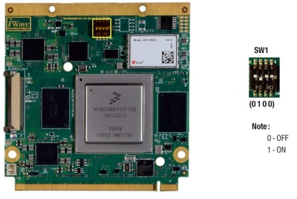
SW1-Boot Selection Switch
SW5-Boot Selection Switch.
Table 1: Boot Media Switch Settings
Debug Port Setting
Connect Type-A end of USB cable to PC and Micro-B end of USB cable
to Development platform’s debug Micro USB connector(J2) as shown
below .
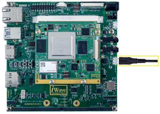
SW1-Boot Selection Switch
Use one of the terminal application depending on the operating system
of the host machine:

On the command prompt of the Linux host machine, run the following command to determine the port number:
$ ls /dev/ttyUSB*
The smaller number is for Arm® Cortex®-A53 core and the bigger number is for Arm® Cortex ®-M4 core.
Minicom
Use the following commands to install and run the serial communication program (minicom as an example):
- Install Minicom using Ubuntu package manager.
$ sudo apt-get install minicom
- Launch Minicom using a console window using the port number determined earlier.
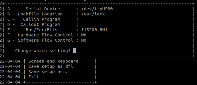
$ sudo minicom -s - Configure Minicom as show in below figure
Next step is to Power ON the board.
Install the driver for Debug USB Port in Host PC/Laptop using the below link.
http://ftdichip.com/drivers/vcp-drivers/
- Download Tera Term. After the download, run the installer and then return to this webpage to continue.
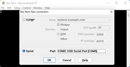
- Launch TeraTerm. The first time it launches, it shows the following dialog. Select the serial option. Assuming your board is plugged in, there should be a COM port automatically populated in the list.
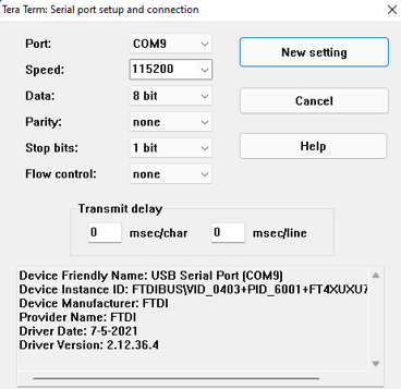
- Configure the Serial Port Settings.
Go to Setup → Serial Port and change the settings as shown below.
- Verify that the connection is open. If connected, Tera Term shows something like below in its title bar.
- Next step is to Power ON the board.
Install the driver for Debug USB Port in Host PC/Laptop using the below link.
http://ftdichip.com/drivers/vcp-drivers/
- Download PuTTY. After the download, run the installer and then return to this webpage to continue.
- Launch PuTTY by either double clicking on the executable file you downloaded or from the Start menu, depending on the type of download you selected.
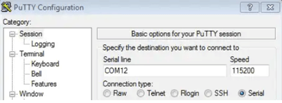
- Configure In the window that launches. Select the Serial radio button and ether the COM port number that you determined earlier. Also enter the baud rate, 115200
- Click Open to open the serial connection. Assuming the board is connected and you entered the correct COM port, the terminal window opens. If the configuration is not correct, puTTY alerts you.
- Next step is to Power ON the board.
Powering ON
Connect the Power supply plug to the Power connector (J4) of the DevKit as shown below and switch ON the power supply. Once power is applied to the Kit, the power LED will glow as shown in the below image.
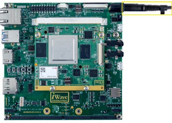
Warning:
- Do not try to connect any other Power Supply other than supplied along with i.MX 8 QM/QP Qseven DevKit.
- Contact iWave, if power LEDs are not glowing.
Boot screen
Users must go through the “Software User Guide” and get familiar with the software section of iW-RainboW-G27M-i.MX_8 QM_QP-Qseven Devkit
Operating System Support

Power is applied to the DevKit & once the boot get success, depending upon the supported Operating systems and boot loader on particular Delivery, boot messages being prompted in the terminal window as shown below. Press Enter key in terminal and done with test environment setup on particular delivery.
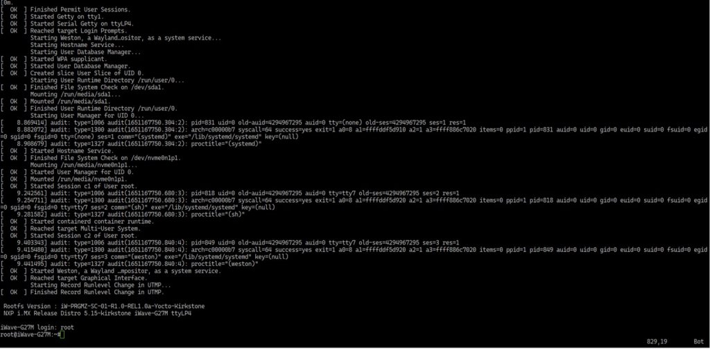
Boot Screen (Linux)
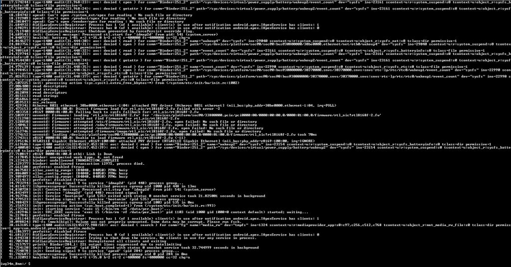
Command Prompt (Android)
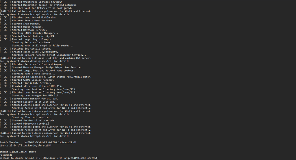
Command Prompt (Ubuntu)
Linux Home screen
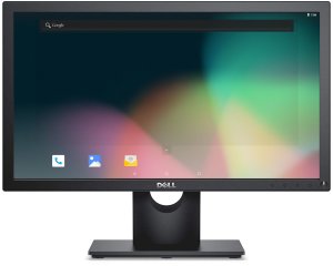
Android Home Screen
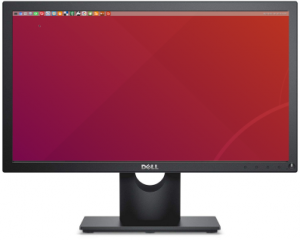
Ubuntu Home screen


