
Get started with i.MX 8 QM/QP Pico ITX Single Board Computer
Unpacking
Remove the SBC from the box and place it above the ESD free area. Use anti-static pad/mat with proper grounding to place the Development Platform. Also make sure that, below deliverables are received without any physical damage.
Development kit contains:
- i.MX 8M QM/QP Pico ITX SBC
- 12V, 2A Power Supply
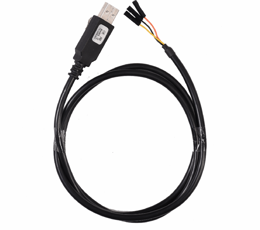
- Debug cable (3V3)*
- Wi-Fi BT Antenna*
- Safety guidelines
- Fan
* Optional


SAFETY GUIDELINES
i.MX 8M QM/QP Pico ITX SBC
12V, Power Supply


Wi-Fi BT Antenna*
Debug Cable*
FAN
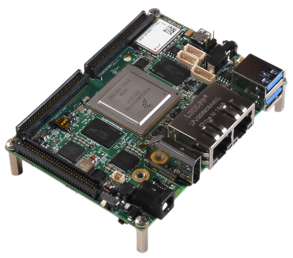
Get to know

i.MX QM/QP Pico ITX SBC – Top view
1. Power IN Jack
4. Dual Ethernet Jack
7. Line in Header*
10. RS232 Header
13. CAN Connector
16. Wi-Fi Antenna Connector
19. Expansion connector-2
22. LPDDR4
2. FAN Header
5. Dual USB 3.0 Connector
8. RTC Header
11. Debug UART Header
14. JODY W2 Wi-Fi BT
17. Expansion connector-1
20. Boot Mode Switch
23. Power Switch
3. HDMI TX Connector
6. USB OTG Connector
9. Audio IN/OUT Jack
12. HDMI RX Connector
15. BT antenna connector
18. i.MX 8M QM/QP CPU
21. Expansion connector-3

i.MX QM/QP Pico ITX SBC – Bottom view
24. eMMC
27. Reset Switch
30. Tamper connector
33. Nano SIM card Connector
25. JTAG Header
28. M3 Mounting Hole
31. Micro SD Connector
34. ON/OFF Switch
26. Pin eDP Connector*
29. M.2 Key B Connector
32. USB 3.0 Header*
Boot Switch Setting
Make sure On-Board Switch (SW1) is set properly as shown below image.

SW1-Boot Selection Switch
Table 1: Boot Media Switch Settings

Debug Port Setting
Connect Type A end of TTL-232R-RPI cable to PC and 3pin (100mil) Berg house end of TTL-232R-RPI cable to Expansion Connector (J7) as shown below.

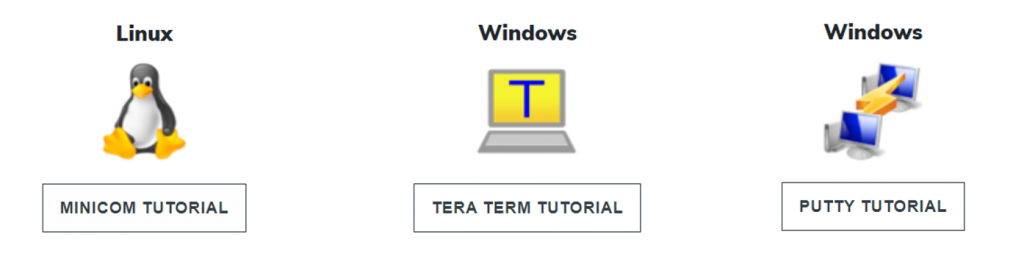
Use one of the terminal applications depending on the operating system of the host machine:
Powering ON
Connect the Power supply plug to the Power connector (J17) of the SBC as shown below and switch ON the power supply. Once power is applied to the SBC, the power LED in the SBC will glow as shown in the below image.

Warning:
- Do not try to connect any other Power Supply other than supplied along with i.MX 8M QM/QP Pico ITX SBC.
- Contact iWave, if power LEDs are not glowing.
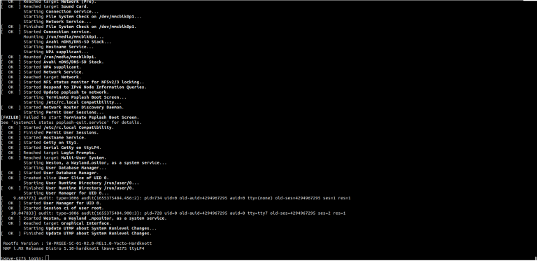
Boot screen
User must go through “Software User Guide” and get familiar with software section of iW-RainboW-G27S-i.MX 8M QM/QP ITX Pico SBC.
Operating System Support

Power is applied to the SBC & once the boot get success, depending upon the supported Operating systems and boot loader on particular Delivery, boot messages being prompted in the terminal window as shown below. Press Enter key in terminal and done with test environment setup on particular delivery.
Command Prompt (Linux)
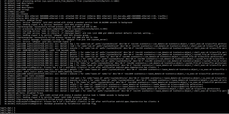
Command Prompt (Android)
Linux Home screen
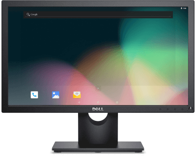
Android Home Screen
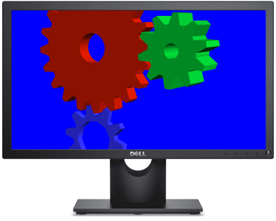
QNX Home Screen
Ubuntu Home Screen